Much much nicer than the VibroKeyer I had been working with.
This makes me want to practice now.
Just received my new Key, it’s absolutely BEAUTIFUL! I’ve been practicing on it for about an hour this afternoon, it’s so smooth & precise… truly love it.
Steve, The slater slate key came in the mail today. Beautiful work, and its sends perfectly like the others I have of yours (Green Machine, TItan and the old TBFB). Thank you again for picking such a fine piece of VT slate to work with.
Hi Steve. I’ve been using the key for a few months now and really enjoying it. Has helped with On the Air clarity and ,in CW training, trying to increase my speed and comprehension. It has been a real joy to use. Very easy to adjust and has been a great addition to the shack. I Just wanted to express my appreciation, especially on the Quality Workmanship that it represents.
Hi Steve just wanted you to know I love this key I’m giving it great reviews in my orbit thanks again !!
Hello Steve san,
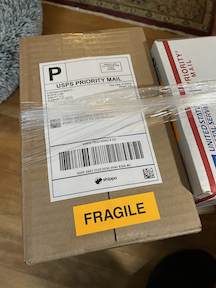
I have received the key today.
It is so beautiful, and I am looking forward to use it.
I appreciate your thoughtfulness.
Package arrived Saturday. Unwrapped this morning. Everything I expected and then some. Thank you for the quick service.
I received my beautiful burgundy cootie today! I have never seen one of your keys or used one, but your design makes sense to me! Most cooties I have used have a hard stop on each side so you get a click-clack sound, but your design has a soft stop and sounds great! I plugged it in and worked a couple stations right away! So, thanks and 73
Hi Stephen – thank you for this beautiful key. I just made my first QSO with it and it’s a pleasure to operate and truly one of a kind. 73
Hi Steve – wanted to send you a quick note letting you know I received your key today. It is beautiful! Thanks a bunch, your craftsmanship is spectacular!
Took the key down stairs and practiced with it for about half an hour. My first time ever trying to use a cootie key. What an experience. The key feels so smooth and precise just as you set it up. It’s going to take some practice to get sending down reliably but I can see this cootie keying is very effective. Just need to put in the practice time.
Thanks so much for such a fantastic key!!!
Already I have noticed I make less mistakes with your key than with the others especially on S’s and H’s. Wish me pleasant Morsing on the bands.
Steve I just received my new FAT BOY key and I LOVE it it is exactly what I have been searching for, a little added weight would be good but not a major issue.
I would be glad to give a superior review on this key if you would like it.
Great workmanship, classie look and works GREEEAAT. 😜😋😜
Best day was 5 marathons!
I think a great deal off you! When we first talked you told me about the horizontal and it’s history. You were so right about it would help with wrist pain! After 5 weeks straight of 1 to 5 marathons a day without pain, I’m thrilled with your design!
Best wishes for your continued success!
WOW ! ! ! WOW ! ! ! WOW ! ! !
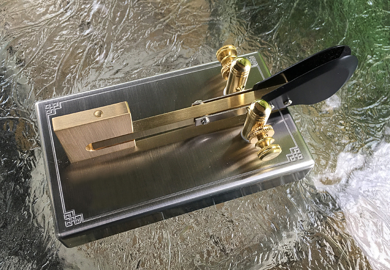
I just received my W1SFR Sideswiper Paddle and it is the most beautiful thing I have ever seen. It is really something to be proud of and I am. I especially like what you engraved on the brass plate for me.
Wow Steve! Your key just arrived, it’s a work of art!
I can only say “WOW”. It is beautiful, but is even more beautiful when pounding out code. It is smooth and stable with no tendency to bounce. It is easy on the eye and on the hand. I love it! Thanks for building such a high quality key.
These one day will be collector pieces, I really believe that.
Hi Steve,
Having had the key a while now I can give you my opinion and observations as a user.
The build quality is excellent, you have done a great job.
Aesthetically the key looks very pretty and totally different from the heard.
It is a pleasure to use but most importantly it has the correct FEEL, light touch and very easy to use fast or slow.
Set up for operator preference is a breeze and it maintains the settings too.
An unexpected bonus is that it does not appear to make any mistakes when sending, so good job Steve and a big thank you from an avid morse junky, 62 years of practice under my belt, military, commercial and now the hobby.
I am not an experienced ham, and actually learning CW through CWOps CWA and the LICW Club offerings. However, I have been struggling with my second-hand Begali HST. It just seems to require a lot of effort for my 75 year old hands. The FATBOY is so effortless and just feels right. I know it will take a few minutes or so to adjust but I am impressed already. Can’t wait to show my CW buddies over Zoom tonight. Expect more orders!